|
|
 |
|
|
|
|
|
|
|
 |
 |
 |
|
|
|
UTE BULLBARTM
Ford Super Duty Series Mounting Instructions
|
|
|
|
|
|
|
|
|
|
|
|
|
|
|
|
|
|
Ford Super Duty F250 / 350 / 450
TOOLS
-
10 mm Socket, 10 mm Spanner
18 mm Socket, 18 mm Spanner
19 mm Socket, 19 mm Spanner
Torque Wrench
Phillips Screwdriver
|
|
|
|
|
|
|
|
|
|
|
|
|
|
|
|
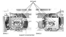
Diagrams 1 and 2
Click on thumbnail for enlarged photo
|
|
INSTALLATION
1. Remove existing bumper.
2. Unbolt brackets from back of BullBar. Leave middle support crossmember in place.
3. Bolt brackets to front of chassis with M12 x 40 bolts, ø12 structural washer under bolt & under nut, & M12 nyloc nuts. Do not tighten (refer to diagram 1 & 2).
NOTE: If fitting winch box, fit top bolts only.
4. Centralize brackets relative to the body, set top of bracket 70mm to underside of grille (refer to Diagram 1) and tighten [(torque 77Nm (57 ftlb)]

|
|
|
|
|
|
|
|
|
|
|
|
|
|
|
|

Diagram 3
Click on thumbnail for enlarged photo
|
|
IF NOT FITTING WINCH, PROCEED TO STEP 25
IF FITTING WINCH, PROCEED AS FOLLOWS
5. Remove support crossmember from between mounting brackets and discard.
6. Bolt winch box in between mounting brackets, level and flush with top of bracket (refer to Diagram 3). Use 7-M12 x 40 bolts each side with ø12 washers under bolt and under nut, and M12 nyloc nuts [(torque 77Nm (57 ftlb)]
7. Remove tow hooks from chassis.
8. To left side, fit tow hook bracket supplied as shown (refer to Diagram 3), using 2 - M12x50 bolts each side through 2 bottom mounting bracket slots with structural washers & nyloc nuts. Tighten.
9. Replace tow hook on top of bracket and bolt through from bottom of chassis using 3 - M12x60 bolts, spring washers and flat washers.
10. To right side, fit tow hook bracket supplied using 2 - M12x50 bolts each side through 2 bottom mounting bracket slots with structural washers and nyloc nuts. Tighten.
11. Do NOT refit tow hook to this side. Bolt through to bracket from bottom of chassis using 3 - M12x60 bolts, flat washers under bolt and nut, and nyloc nuts.
12. Fit winch into the winch box using the 4 bolts supplied with the winch.
|
|
|
|
|
|
|
|
|
|
|
|
|
|
|
|
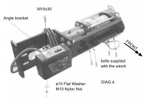 Diagram 4 Diagram 4
Click on thumbnail for enlarged photo
|
|
13. Fit angle bracket (supplied in bolt kit) to back of power control box and then mount to front of right hand mounting bracket (refer to Diagram 4) using M10x30 bolt, ø10 flat washers under bolt and nut, and M10 nyloc nut.
14. Connect all winch cables and wiring as per instructions supplied with the winch.
15. Cut rubber bands securing winch cable and pull the end of cable through the front hole of the winch box.
|
|
|
|
|
|
|
|
|
|
|
|
|
|
|
|
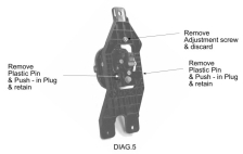 Diagram 5
Click on thumbnail for enlarged photo
|
|
16. Remove driving light from plastic support bracket. Pull out plastic pins and plugs from bottom of light pivot and retain, and remove adjustment screw and discard (refer to Diagram 5).
|
|
|
|
|
|
|
|
|
|
|
|
|
|
|
|
 Diagram 6 Diagram 6
Click on thumbnail for enlarged photo
|
|
17. Assemble adjusting screw supplied onto light as shown (refer to Diagram 6) and tighten nyloc nut until firm so that adjusting screw can still turn.
|
|
|
|
|
|
|
|
|
|
|
|
|
|
|
|
 Diagram 7 Diagram 7
Click on thumbnail for enlarged photo
|
|
18. To assemble light onto front of winch box, insert push-in plastic plugs and pins into pivot bracket, swing light up into position and screw adjusting screw into top bracket (refer to Diagram 7).
|
|
|
|
|
|
|
|
|
|
|
|
|
|
|
|
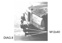 Diagram 8 Diagram 8
Click on thumbnail for enlarged photo
|
|
19. Lift BullBar into position, carefully over lights and fit 6 - M12x40 bolts through mounting gussets on BullBar (refer to Diagram 8). Adjust BullBar level to body and tighten in position [torque 77Nm (57ftlb)].
|
|
|
|
|
|
|
|
|
|
|
|
|
|
|
|
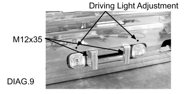
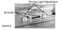 Diagram 9
Click on thumbnail for enlarged photo
|
|
20. Pull winch cable through and fit Fairlead Rollers onto the front of winch box using 2 - M12x35 bolts, spring washers, and flat washers (refer to Diagram 9).
21. Attach winch hook to winch cable.
22. Reconnect driving lights and adjust if necessary by using a screw driver through hole in front of bumper (refer to Diagram 9).
23. Replace rubber stone guard under radiator, to bottom of BullBar with 3 - M6 x 20 bolts.
24. IMPORTANT: Read Winch Manual thoroughly before operation.
|
|
|
|
|
|
|
|
|
|
|
|
|
|
|
|
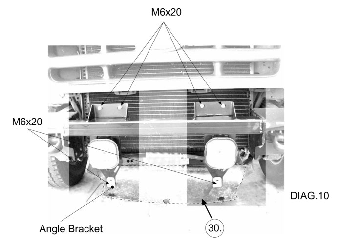
 Diagram 10
Click on thumbnail for enlarged photo
|
|
IF NOT FITTING WINCH
25. Fit driving light support brackets into position as shown with M6x20 bolts but leave loose (refer to Diagram 10).
26. Fit angle brackets onto bottom of driving light support brackets with M6x20 bolts and leave loose (refer to Diagram 10).
|
|
|
|
|
|
|
|
|
|
|
|
|
|
|
|
|
|
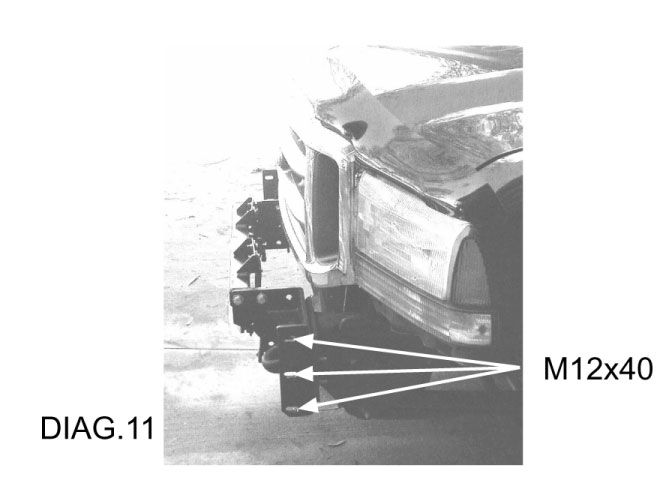
27. LIft BullBar into position, carefully over lights and fit 6 - M12x40 bolts through mounting gussets on BullBar (refer to Diagram 11). Adjust BullBar level to body and tighten in position [torque 77Nm(57ftlb)].
28. Bolt driving light angle brackets to BullBar with M6x20 bolts and tighten all bolts.
29. Reconnect driving lights and adjust if necessary using a screwdriver up behind the lights.
30. Replace rubber stone guard under radiator to bottom of BullBar with 3 - M6x20 bolts (refer to Diagram 10).
Return to BullBar main page
|
|
|
|
|
|
|
|
|
|
|
|
|
|
|
|
|
|
Call toll-free 1-TON-UTE-BEDS or 1-866-883-2337
|
|
|
|
|
|
|
|
|
|
|
   
|
|
|
|
|
|
|
|


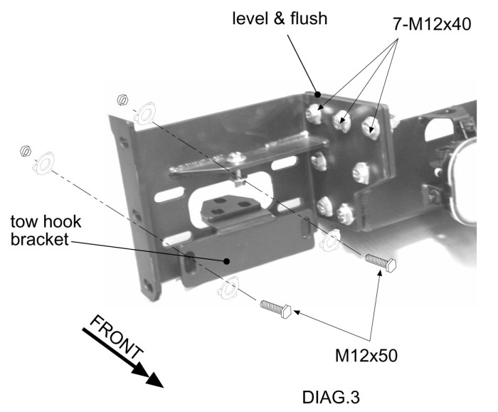
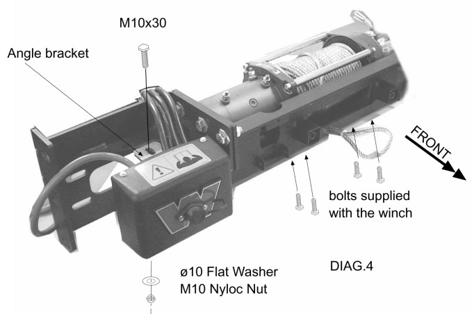 Diagram 4
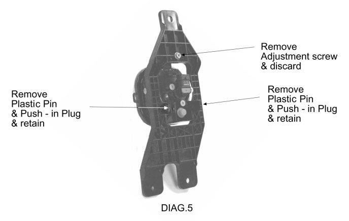
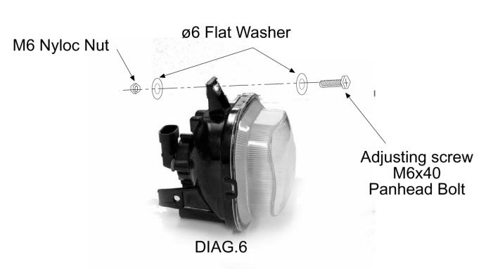 Diagram 6
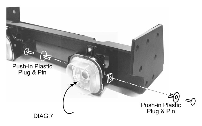 Diagram 7
 Diagram 8